
The following subsections will guide you through the installation and general setup of your Robotiq 2-Finger Adaptive Robot Gripper.
Warning
Before installing:
Warning
When installing:
|
Robotiq 2F-85 Adaptive Gripper |
Robotiq 2F-140 Adaptive Gripper |
|---|---|
|
|
The following tools are required to install the 2-Finger Adaptive Gripper:
Optional tools if installing finger kits: AGC-FIN-KIT-085 or AGC-FIN-KIT-140:
Optional tools if installing other fingertips: AGC-TIP-204-085, AGC-TIP-205-085, AGC-TIP-420-140, AGC-TIP-420-140
The following parts are required for setup :
The Gripper needs to be supplied by a DC voltage source. This power supply is not included with the Gripper. Required power supply must match the Robotiq device. The following table shows the specifications with regards to the power supply required to operate the Gripper and the optional Robotiq Controller.
Table 3-1: 2-Finger power supply requirements.
Info
1 Suggested fuse is a: Phoenix Contact # 0916605 2 A thermal, use AWG #20 wiring.
Warning
If your power supply could exceed the specified regulation, over-voltage protection is required.
Robotiq recommends the use of the following power supplies:
Tip
Optional Robotiq Universal Controller can use the same power supply.
|
CONDITION |
VALUE |
|---|---|
|
Minimum storage/transit temperature |
-30°C [-22°F] |
|
Maximum storage/transit temperature |
60°C [140°F] |
|
Minimum operating temperature |
-10°C [14°F] |
|
Maximum operating temperature |
50°C [122°F] |
|
Humidity (non-condensing) |
20-80% RH |
|
Vibration |
< 0.5G |
|
Other |
|
Table 3-2: Environmental and operating conditions of the 2-Finger Adaptive Gripper.
Depending on your order, you may or may not have fingers already mounted on the Gripper. The first step of installation should be to install the fingers. Refer to the figure below for finger placement. To do so :
Fig. 3-1: 2-Finger Adaptive Gripper installation.
Depending on your options, you may have fingertips to install. The second step of the installation should be to install the fingertips. To do so:

Fig. 3-2: Installing the fingertips on the Gripper
An optional protector kit (AGC-PRO-KIT-V4) can be ordred to cover the fingers of the 2F-85 and therefore protect users and assets against pinch points.
You can install them using eight (8) M3 screws.
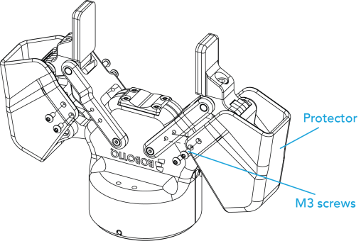
Fig. 3-3: Protector Kit Installation
You must use a coupling to attach the Gripper to the robot.
Here are the steps to follow to mount the Gripper on the robot (exploded view in the figure below). Note that all screws must be locked in place using medium strength threadlocker.

Fig. 3-4: Installing a Gripper on the robot wrist
When installing multiple grippers on one robot, every gripper must have its own coupling.

Fig. 3-5: Exploded View of a Dual Gripper Setup
Fig. 3-6: Exploded view of a dual gripper setup
Power and communication are established with the 2-Finger Adaptive Robot Gripper via a single Device Cable. The Device Cable provides a 24V power supply to the Gripper and enables serial RS485 communication to the robot controller. An optional Robotiq Universal Controller may be used between the Gripper and the network / robot controller if fieldbus communication is required.
Info
RS485 signals (485+, 485- and 485 GND) are isolated from the main 24V power supply. 4 GND can be connected to any other ground reference as long as the voltage potential between the grounds does not exceed 250V. Grounding reference is at the user's discretion.
Gripper grounding is optional and is done via the robot ground. The coupling indexing pin (dowel) is the ground connector. Gripper coupling, chassis and proximal phalanx are linked as illustrated in the figure below. They link through the coupling indexing pin to the robot ground. Proximal bars, distal phalanx, fingertip base and fingertips are isolated.
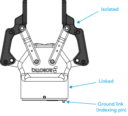
Fig. 3-7: Robotiq 2-Finger electrical isolation / grounding.
The Gripper interfaces with its coupling via a 10-spring pin connector located on its outer surface.

Info
The coupling used in the figure above is used for reference only and corresponds to bolt pattern ISO 9409-1-50-4-M6.
If a Robotiq Universal Controller is used, please refer to the Robotiq Universal Controller manual. The figure below represents the wiring schematic of the 2-Finger with device cable, power supply, fuse (please refer to the Required Tools and Equipment section) and grounding.
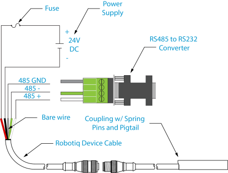
Fig. 3-8: Pigtail cable and device cable wiring schematic.
Fig. 3-9: Robotiq 2-Finger with pigtail cable and device cable wiring schematic.
Warning
Use proper cabling management. Be sure to have enough forgiveness in the cabling to allow movement of the Gripper along all axes without pulling out the connectors. Always protect the controller-side (robot side) connector of the cable with a strain relief cable clamp.
The figure below represents the 2-Finger pigtail connector from the coupling (AGC‑CPL‑XXX), device cable - robot side (CBL‑COM‑2065‑XX) and their associated pinout.

Fig. 3-10: Pinout of the 2-Finger pigtail and device cable.
If additional cable is used, suggested cable specifications are as follows:
Power supply, fusing:
Connect the white, green and bare wires to the Robotiq RS485 to RS232 signal converter (ACC-ADT-RS232-RS485) as shown in the figure below.
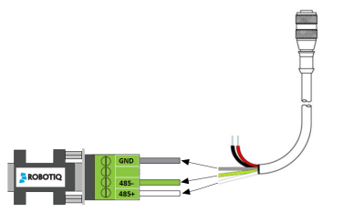
Fig. 3-11: Gripper Cable to RS485/RS232 Converter
Also connect the red (24V) and black (0V) wires in the controller according to the figure below.
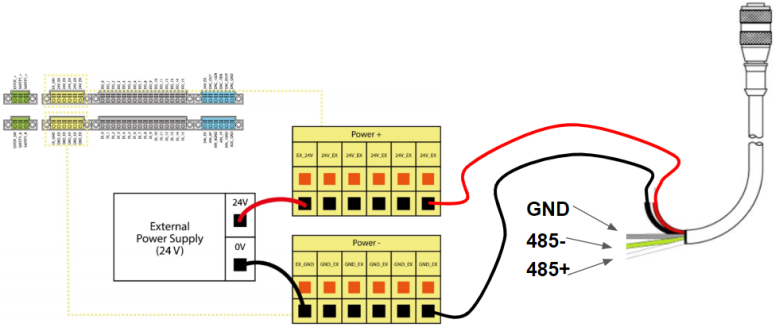
Fig. 3-12: Gripper Cable to Terminal Connector on the Controller
It is possible to connect multiple grippers on the same robot. Only one RS485 to RS232 converter (ACC-ADT-RS232-RS485) must be used. Use M12 splitters (ACC-SPLIT-M12-2:1) to connect all the grippers pigtails to one 10m cable (CBL-COM-2065-10-HF) that connects to the RS485 to RS232 converter.

Fig. 3-13: Multiple grippers wiring